1. External LED
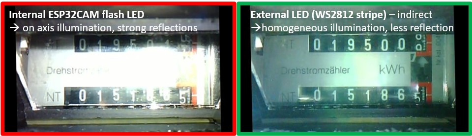
The internal flash LED is very close to the camera axis. This results in reflection, especially in case of flat glass surfaces such as for power meters. To circumvent this problem, it is now possible to control external LEDs, which than can be places somewhere else in the setup. As not simples LEDs are used, but RGB LEDs with a digital interface like WS2812 not only the position, but also the color and intensity of the illumination can now be adjusted. The following image shows a direct comparison of the "old" internal flash LED and two off axis LEDs.
There is also a new meter adapter available. This has two features: designed for small clearings in front of the meter and prepared for WS2812 LEDs.
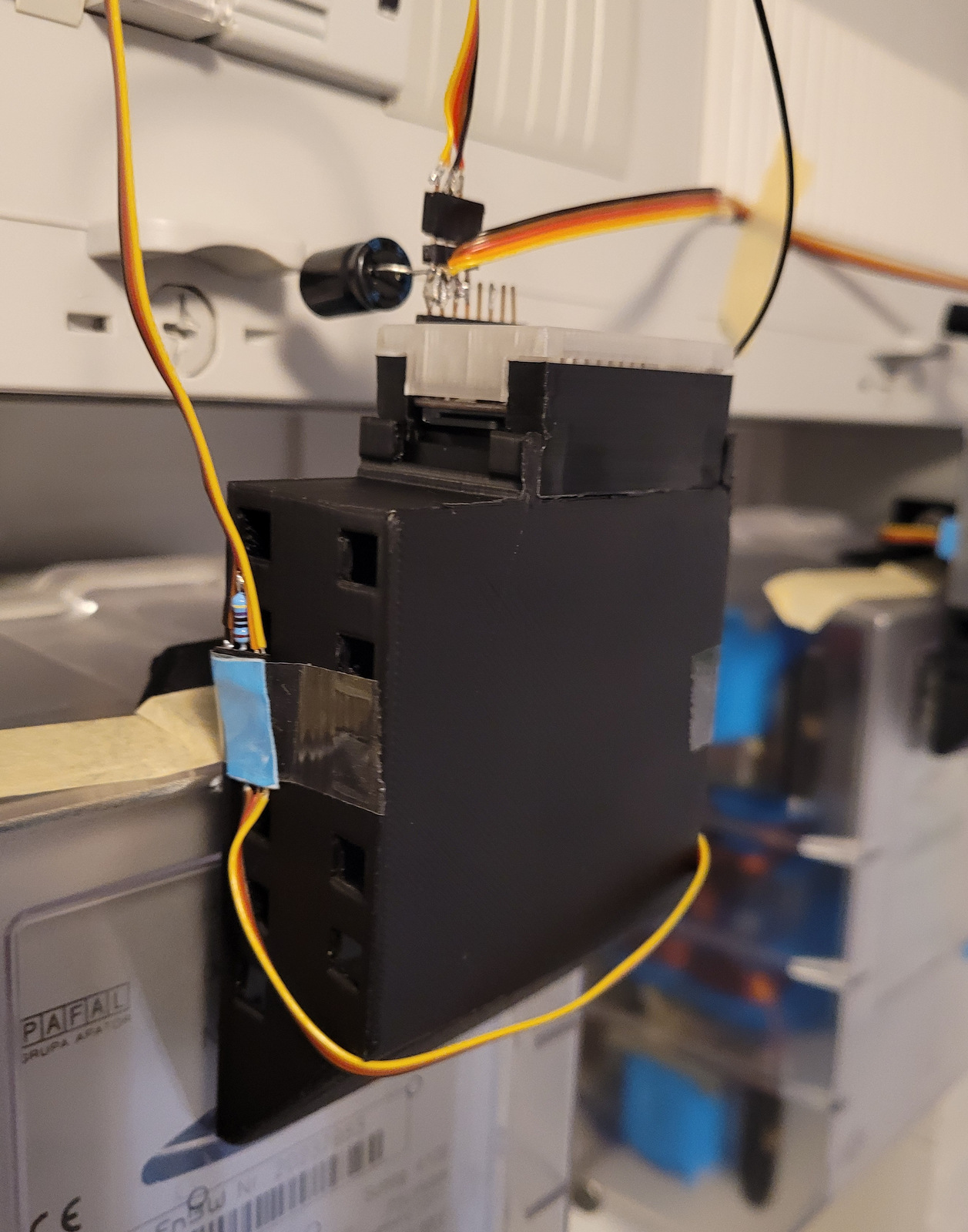
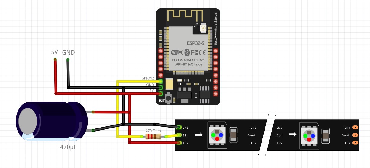
1.1 1. Hardware installation of the LED stripe
The control line of the LED stripe is connected with a 470 Ohm resistor to the GPIO12. For power supply stabilization a capacitor between 5V and ground is recommended. Here a 470µF polymer capacitor is used. As a power supply a 5V from the ESP32 is used like in the following wiring.
1.2 2. Software configuration
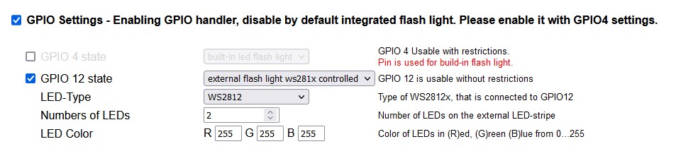
The handling of the WS2812 LED controller needs some other libraries, therefore it is controlled within a dedicated section called GPIO Settings. The external LED stripe is connected to GPIO12. After activating the "GPIO Settings" section, the internal flash is per default disabled. In order to activate the external LED, you need to activate GPIO 12 state and select "extern flash light ws281x ...".
| Parameter | Meaning |
|---|---|
| LED-Type | There are several types of controller implemented: WS2812(B), WS2813, SK6812 |
| Numbers of LED | Number of LEDs on the LED stripe |
| LED Color | The color and intensity can be controlled directly by a red/green/blue value, each within the range from 0 (off) to 255 (full) |
Enabling the GPIO settings automatically disables the flash LED. Therefore you can enable it here manually by checking GPIO4 and choose "build-in led flash light". It is not recommended to use both illumination parallel.